Why can I not see feature shades?
Feature shades are not shown in the visualisation. Feature shades are parametrically calculated shading devices. Although they have an effect on the simulation, they are not physically modelled as other surfaces are.
Why can I not see external shades that were added in the 3D Modeller?
External shades are not shown in the visualisation. Although they are physically modelled much as other surfaces are, their co-ordinate geometry is not included in the TBD file.
Why can I not see airscoops/sunscoops?
Airscoops and sunscoops added by the Passivent Tool will not be visible in the visualisation. Their zones and surfaces are modelled much as any other surfaces are, but their co-ordinate geometry is not generated.
Why does my notional/baseline building not show altered geometry?
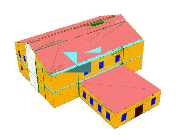
When Tas alters geometry parametrically, such as during the generation of a notional or baseline building, surfaces will be added, removed or changed. However, the co-ordinate geometry is not altered. Added surfaces will not be shown in the visualisation, and surfaces with changed areas, altitude ranges &c. will appear in the position they were in the source file. They are of course modelled correctly according to their properties – the co-ordinate geometry only affects their visualisation.
Why is there no visualisation available for my building?
This can occur with TBD files generated by some external programs. If a program does not export co-ordinate geometry, then it will not be able to be shown in the visualisation.
Why does the visualisation show distorted surfaces?
Some models produced by the DOE Importer or IDF Importer may have unusually positioned surfaces, usually floors or ceilings. This is because the geometry contained in the original file (.inp or .idf file) was insufficient to produce complete co-ordinate geometry for these surfaces. Properties needed for reasonable simulation are not affected by this; merely their appearance in the visualisation.
Why are there gaps visible at the corners of zones?
On occasion, the 3D Modeller produces surface geometry such that edges or vertices of adjacent surfaces are not coincident. This results in visible gaps at those points. This does not mean that those gaps are physically modelled – refer to the surfaces table to see any actual null surfaces. It may also result in a slight difference between the modelled orientation/inclination of a surface and its apparent orientation/inclination. Again, this is not significant to the simulation.
Why do surfaces appear chopped into many triangles or protrude from the model?
On a small number of graphics adapters, particularly much older or less powerful ones, surfaces will appear divided into triangles by lines, or have incongruous extended surfaces. It is advisable to check that your graphics drivers are up to date. This will not always solve the issue, as it is a result of the graphics adapter’s rendering implementation.
The visualisation is very slow to move/rotate/respond. What can I do to make it faster?
The ‘Faster Interactive’ option, accessible through the right-click menu on the visualisation, will simplify the drawing of the model during any camera movement. This is enabled by default.
It is also advisable to check that your graphics drivers are up to date.
Why are there large spaces visible between zones?
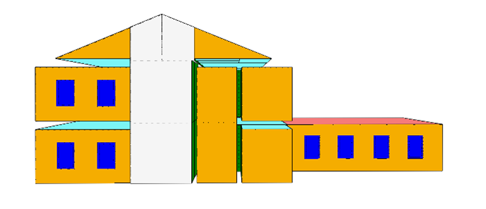
The visualisation shows the internal faces of zones – the bounding faces of the spaces. This means that the thickness of building elements between zones will appear as gaps. This will be more noticeable where the building element is thicker – for example, where they include ceiling voids.
Why is a single surface in the surfaces table/output selection showing as multiple surfaces in the visualisation?
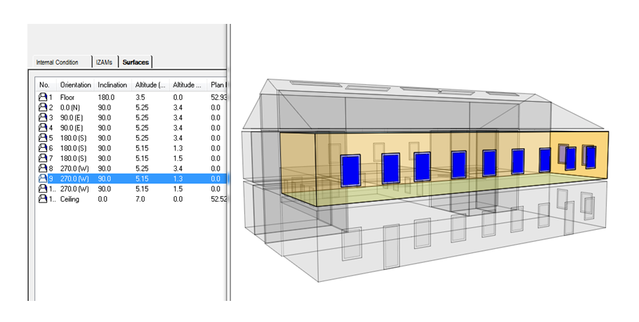
When the 3D Modeller generates a TBD file, it may combine surfaces with identical properties (the same building element, orientation, inclination, altitude and so on). One surface with their combined area will behave identically to multiple separate surfaces, but is simpler for the simulation calculations to handle. The separate surfaces still have their co-ordinate geometry stored, however, so will be shown in the visualisation.
Why are surfaces showing noise patterns or changing colour depending on the camera angle?
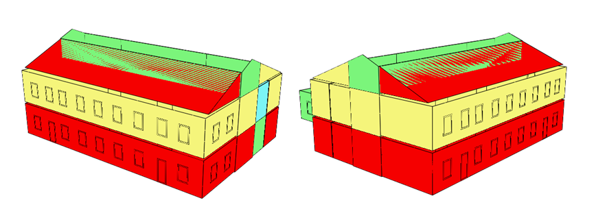
This will occur when two or more surfaces occupy the same space. The renderer cannot determine which is closer to the camera, and so will not reliably show one on top of the other - this is known as z-fighting.
There are three situations in which this can happen:
Why can I not see window panes?
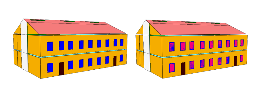
In versions of Tas prior to version 9.2.1.4, The 3D Modeller did not export a ‘hole’ polygon in window frames – areas were still correct, however. This meant that window panes may be obscured by or z-fight with their frames (The right-hand image above has had the window panes coloured pink to show this). If you re-export the 3D model and merge with the TBD file, it will add the holes.
Why do IZAM flows not show up as arrows in the results viewer visualisation?
IZAMs cannot be shown as flow arrows in the visualisation. IZAMs are not modelled flows through surfaces – they are a direct movement of air. Although their effects are included, they have no geometric basis as aperture flows do.
Why can’t I see a particular surface?
Why can’t I see flow arrows?