Miscellaneous

Frequently Asked Questions

If you have a question about the software, check out the frequently asked questions below. If you can’t find the answer you’re looking for, please contact support.

Results Viewer

Open your TBD file and on the tree-view click Zone Groups. The table displayed on the right-hand side contains a column header denoted Output. If any of the entries in this column read No then the corresponding zone will not be outputted to the Simulation Data file, or TSD. The zones with a Yes displayed in the Output column will be outputted.

If you have created a new building element to represent an aperture, rather than a window type, then you should verify that the building element does not have the Ground checkbox enabled.

If you have created a window type, then you should check that the window has not been applied to a surface which has been defined as being in direct contact with the ground. Again, check that the input surface does not have the Ground checkbox enabled.

This should be verified in the 3D Modeller.

In the Building Simulator, set up an aperture type and apply it to the window-pane, or the equivalent building element.

You must output aperture data when you simulate your TBD. On the Simulate menu, click Run Simulation. Enable the Output aperture data checkbox on the Simulate dialog or create a surface output specification in your TBD file, making sure to enable the Aperture Data checkbox. Right-click anywhere on the tree-view on the left-hand side and on the context-menu, click Surface Output Spec.

If you do create a surface output specification, then you must apply it to the building element through which you expect to see air flow.

You must also set up the simulation data file, or TSD, to display aperture data in the tabular or graphical results view.

Create a new Output Selection and drag the zone containing the aperture onto the Surfaces table on the output selection.

You must then create an Output Filter and enable the Aperture Flow In and Aperture Flow Out checkboxes on the Surfaces column.

Databases

Their default location is \My Documents\Tas Data\Databases.

The software should be installed on your own user account. If this is not done, then the missing databases will have been saved to the My Documents folder of the person who was logged in at the time of the installation. This will likely be your Systems Administrator.

The Tas Data folder can also be found in the Downloads section of this website.

Part L2 and EPC

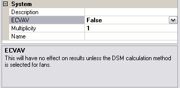
In the Air-side configuration stage of the UK Building Regulations Studio, create a Fancoil system. To specify that the Fancoil has an ecVAV terminal fan, set ECVAV to True in the System properties.

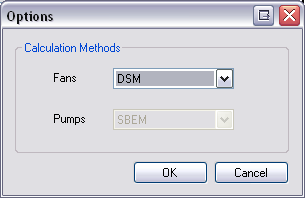
No alteration will be made to your simulation results unless you change the fan calculation method from SBEM (required by NCM Modelling guide in order to produce a BRUKL document) to DSM (our more accurate, hourly Dynamic Simulation Model). You can change this setting in Tools->Options.

With the fan calculation method set to DSM, the ecVAV terminal fans will now vary their speed according to the heating/cooling requirement and you will see a reduction in the auxiliary load, in accordance with the fan power cube law.

However, the BRUKL document will not be created. Instead, a spreadsheet will be created, which will contain the effective seasonal specific fan power (SSFP) for each ecVAV terminal fan.

You should re-enter the SFP for each fan using these calculated SSFP values, then revert the fan power calculation method to SBEM. When you re-run your calculations, a BRUKL document will be generated.

For all systems that include supply air (i.e. all except “Extract Only” and “Occupied and Unheated”), the BRUKL Details contain s section for Demand Control, which is a drop-down menu containing options from the NCM Modelling Guide.

The option you choose will determine the amount of fresh air that is supplied to the zone, in accordance with Table 13 and Equation 13 of the NCM Modelling Guide. Demand control will have an impact on your heating and cooling loads, as the volume of air entering your zone at outside conditions will be reduced.

By default, the studio models this reduction as damper control, whereby the supply and extract fans continue to run at the peak flow rate, but a damper is used to split the air stream and divert air away from the zone. As such, demand control will not have any impact on the auxiliary load associated with the supply and extract fans.

An alternative form of demand control is fan control. In contrast to damper control, fan control involves reducing the supply and extract fan speeds and will result in a corresponding reduction to the auxiliary load. In both cases, you must choose the appropriate demand control option. In the case of fan control, you must also re-calculate a new, lower SFP for the supply and extract fans according to the following, simplified form of Equation 13:

Where Cdc can be found in Table 13 of the NCM Modelling Guide and Dp is the greater of (a) the minimum non-zero occupancy as a fraction of the maximum occupancy or (b) 0.6

Miscellaneous

Please contact support@edsl.net for information on obtaining a replacement dongle.

Obtain new keys via our website if your license is maintained and supported. If this process fails, then there is a possibility that the maintenance and support component of your license has expired.

Copy your Tas Manager ID to support@edsl.net requesting new license keys if your license is NOT maintained and supported, or if you suspect the contact has now expired and has not been renewed.

Install the dongle drivers on your new machine. Click here to find more information on the latest drivers.

Make sure that you create a zip file to reduce overall file size.

You can attach files up to 15MB by email.You can upload files of approximately 25MB to our FTP server using our online form.

If you need to upload larger files, please contact support for additional options.

Note If you are running either the Plant Modelling macro or the UK and ROI Building Regulations macro and you need to upload your project directory to our FTP server, you can significantly reduce the size of your RGinfo folder. Open the macro and on the Project dialog, click the Clear Stored Zone Data button.

Open Tas Manager. The version number is displayed beneath the Tas logo on the right-hand side, positioned beneath the titlebar.

Please look at our BEEM checklist on the ‘validation‘ page of our site.

Open Tas Manager and click Register. The Registration dialog will display either Locked or Dongle beneath the Tas logo.

If Locked is displayed, then your dongle has not been recognised.

This might be due to a fault with the dongle or the port in which it is connected, or the dongle drivers.

First check if the LED light on the dongle is illuminated.

Try an alternative port.

Check the dongle for any visible signs of damage.

Try downloading and installing the dongle drivers from our website.

If the dongle still displays Locked beneath the Tas logo then contact support@edsl.net for details on obtaining a replacement dongle.

If the dongle displays Dongle then contact support@edsl.net who will be able to advise whether your maintenance and support contract has expired.

Without a valid maintenance and support contract you will not be able to obtain license keys from the EDSL website. Instead, you will need to copy your Tas Manager ID to support@edsl.net. New license keys will then be returned by email.

You can obtain weather data files from the Energy Plus website.

If you have a copy of Meteonorm then you can create weather files from locations around the globe.

Once you have your weather data file, open the Tas Weather Database. On the File menu, click Import Weather Data. An Open dialog will appear. Expand the Files drop-down list and select from Energy Plus weather data (*.epw) or TMY2 files (*.tm2).

For Part L/EPC projects you need to use CIBSE weather data, which has to be purchased separately, from CIBSE.

The surface areas exported to the Building Simulator are taken to be the average of the internal and external surface areas, which provides a reasonable approximation to modelling thermal bridging.

To model the effect of thermal bridging more closely, you can set up a secondary element in the 3D Modeller. To the secondary element you can apply a construction with a U-value different to the construction applied to the main structure.

It is possible to approximate thermal bridging by altering the U-value of the construction applied to the structure, or by modifying the internal and external surface areas so that the average surface area provides a closer approximation.

Can't find what you're looking for?