Planning for Daylight & Sunlight
Right of Light
&
BR09 Site Layout Planning for Daylight and Sunlight
Tas Engineering features tools and a utility to assist with analysing the impact of planned constructions on existing properties.
To analyse the effect of new constructions on existing properties, create two Tas 3D modeller files; one with the existing geometry and one with the proposed geometry. These are then the inputs for the Daylight Analysis Wizard.
Right of Light
The main metric used to assess the risk of a Right of Light violation is Equivalent First Zone. This calculation quantifies how much of a rooms area goes from being adequately lit, to inadequately lit, and how much of an impact this might have.
According to the Right of Light guidance, a space is considered to be adequately lit if it receives more than ~10 lux, though in practice the figure is probably closer to 25 lux1.
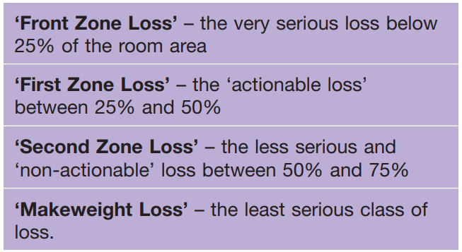
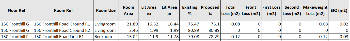
Using the Daylight Analysis Wizard in Tas, you can compare the amount of loss in each of the zones from the table above between two Tas models. The wizard creates a clear table of results in excel format, which is useful for large models…
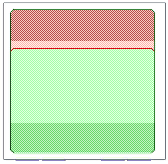
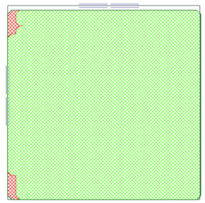
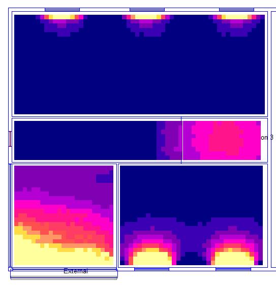
Contour Diagrams
The wizard can also produce contour diagrams in a report summarising the EFZ results for each zone, and all reports can be stored in a single file for efficient project management.
Creating City Geometry
One of the most powerful features of using the 3D modeller for daylight & sunlight planning analysis is the ability to import 3D DWGs as shade surfaces; for more information, see below.
BRE09: Site Layout Planning for Daylight and Sunlight
BRE09 is a guide to good practice with regards to minimising the impact of a new construction on existing buildings. Unlike the right of light calculations, there is no legal obligation to conform to these standards but they are widely used nevertheless.
The guide uses a number of different calculations to help analyse the impact on an existing property and their amenities.
Annual Probable Sunlight Hours
This is a window based calculation that counts how many hours in a year a window receives direct sunlight, taking into consideration the local climate (clouds).
Previously, this calculation was performed by superimposing the view from a window onto a sunlight availability indicator, which is a special diagram that visually plots the position of the sun throughout the year during potential sunny hours.
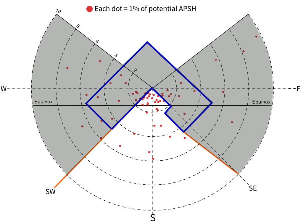
- The traditional method has some serious limitations:
- Poor resolution (each point is worth ~15 APSH hours)
- Only 3 diagrams available (Manchester, London, Edinburgh/Glasgow) & nearest one picked -> inaccurate!
- Diagrams constructed using very old weather data
- Slow!
The APSH method in Tas is different as it uses our advanced daylighting engine:
- Any weather file can be used
- Hourly resolution
- Fast and accurate
Daylight Distribution
The Daylight Distribution calculation seeks to find the no sky line in a property. This is the line on the floor plan that marks the point where you are no longer able to see the sky when looking towards a window.
These calculations were traditionally performed manually using complex diagrams, but in Tas they’re performed using our daylighting engine.
Daylight Factors
Daylight Factor calculations were traditionally performed using a highly simplified formula based on the glazed area of the window, the light transmittance, the total area of the room surfaces and the angle between the top of the window frame and the obstruction outside the window. In simple cases, this method gives a valid indication of the actual daylight factor the space is likely to expect but quickly breaks down when dealing with:
- Complex external and external geometry
- Light reflectance
- Different reflectances for interior surfaces
- Shared light from other spaces
In Tas Engineering, daylight factor calculations can consider light that falls directly on the working plane (no bounce), or can consider light that reaches the working plane after many reflections. It can also take into consideration arbitrarily complex external geometry, and complicated internal geometry too.
Vertical Sky Component
Vertical Sky component is a window based calculation and is defined as the ratio of the illuminance that falls on the centre point of the window to that which would fall on a horizontal plane placed at the same point.
This calculation can be performed directly in Tas using the 3D modeller or using the daylight analysis wizard.
Permanent Overshadowing
Permanent overshadowing calculations are performed on outside amenity spaces such as gardens and courtyards.
The calculation is usually performed on the vernal equinox and tries to ensure that locations receive at least 2 or more hours of sunlight. The result is expressed in terms of the area of the amenity that does meet this requirement.
The Daylight Analysis Wizard
Due to the number and nature of the calculations involved when analysing the impact on daylight, the daylight analysis wizard was created with iterative design in mind. The wizard automatically remembers the inputs each time it is used, so that it is very quick to make a small change and see the effect.
As these calculations usually involve working with hundreds of zones, we made sure it is easy to sort through results and quickly identify where a space is physically in the 3D model.