We will often want to create plant room layouts which are more complex than the ones created by the systems wizard, and split and combine flows to use components on separate branching pipes. There are different ways to achieve this, but also a few potential pitfalls; this guide aims to shed some light on the subject.

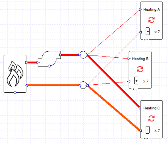
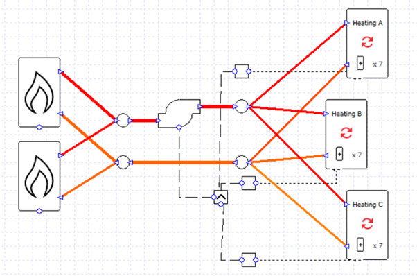
In the image above we have used the wizard to create three heating circuits because we wish to view the results for each collection separately. But what if we want to have the three heating collections on the same heating loop, served by the same heating source? We might decide wouldn’t be appropriate to put the collections in series as the water temperatures into the second and third collections would be too low.
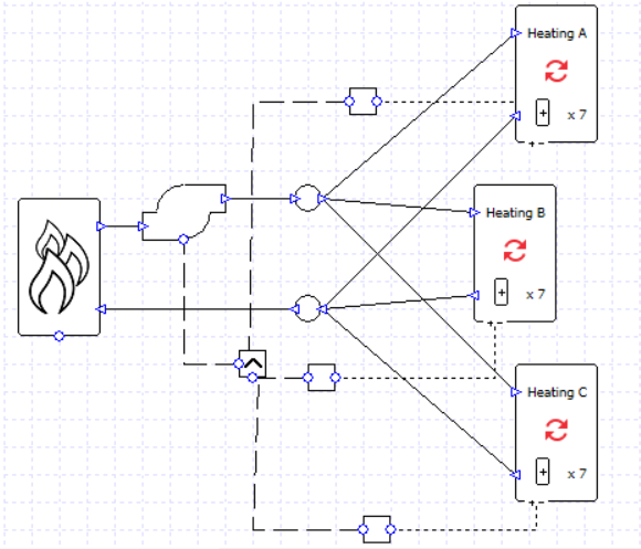
In order to put the collections in parallel we will need to use junctions to split and combine the water flow.
Each collection has a controller checking to see if the load is above zero, and the pump has a “max” controller so that it will run if any signal is greater than zero.
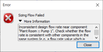
If we’re not careful, however, soon we could start running into problems. Here is one message we might well encounter.
Why has this happened?
Why do we have an inconsistent design flow rate?
Let’s look at the parameters which will affect flow sizing:
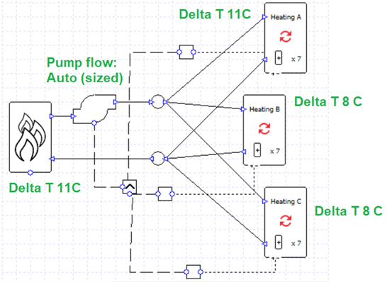
If we calculated the sized flow rates for the boiler and collections from their maximum loads and delta T, for this model we would find:
Boiler: 0.68 l/s
Heating A: 0.16 l/s
Heating B: 0.32 l/s
Heating C: 0.41 l/s
The 0.68 l/s of the boiler does not match the 0.89 l/s total required by the heating collections. This is the inconsistency referred to in the error message. In other words,
0.16 + 0.32 + 0.41 =/= 0.68.
How can it be fixed? We can either balance the equation or we can remove the boiler from the flow sizing altogether. If we set the boiler delta T to “none” then it won’t be used in the pump sizing and it will just accept whatever flow is required by the collections. Alternatively, we could, for example, change the delta T to 11 for the collections currently using 8; when the components have the same sizing parameters the equation will balance:
0.16 l/s + 0.23 l/s + 0.29 l/s = 0.68 l/s
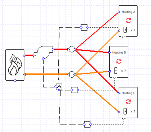
This setup will still work if we want to incorporate varying flow rates; we can assign variable flow capacity to the collections and the flow rate will decrease for lower heating loads.
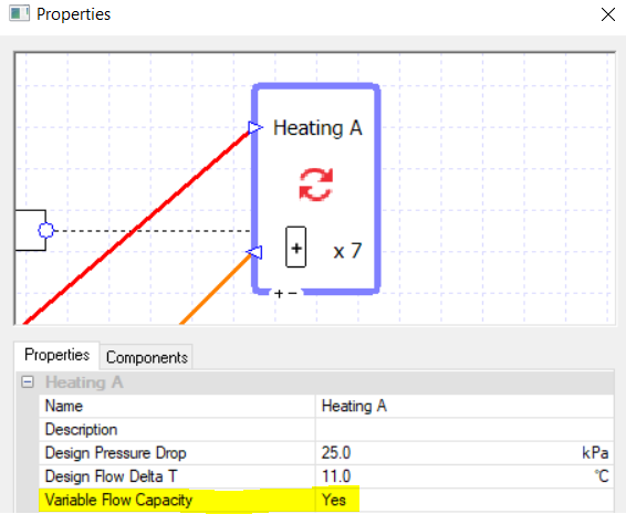
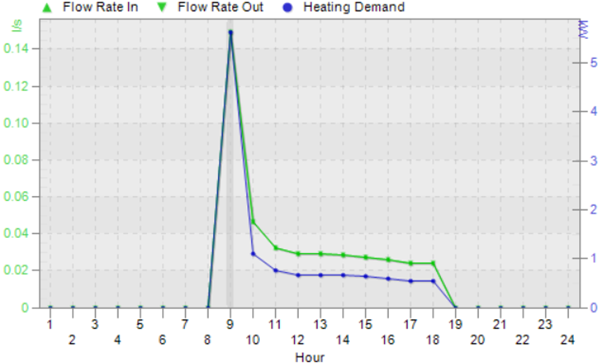
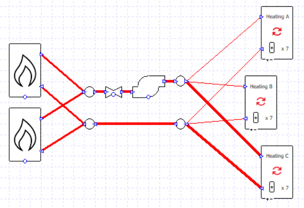
When we’re using the variable flow capacity on all the collections there is no more need for the controllers on the pump; the collections’ capacity will increase or decrease to allow the hot water to flow as and when it is needed, and only where it is needed, for example on this hour when only collection C has a heating load:
If we wanted to, we could take our earlier example and replace the multi-boiler with two boiler components, each with a sizing factor of 0.5, and put them in parallel; as long as the boilers are sized using the same delta T the pump sizing will succeed.
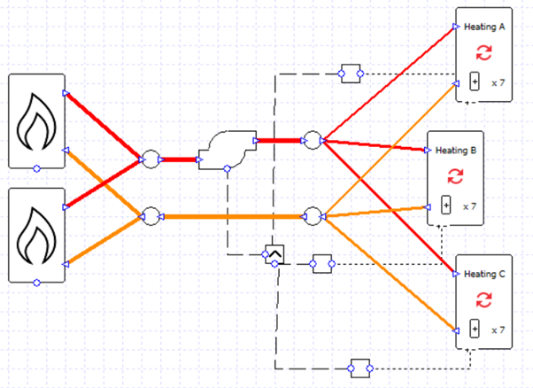
What if we didn’t want to size these flows, and instead we wanted to dictate the pump maximum flow rate and the maximum flow rate which will travel down each pipe? Let’s enter a set value for the pump flow rate and add some valves to the system.
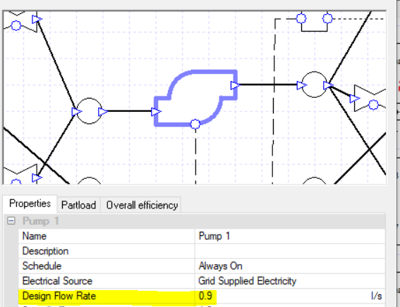
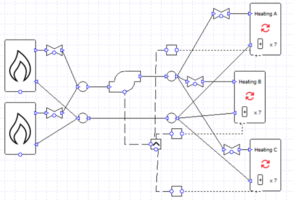
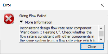
Now we might run into an inconsistent design flow rate issue again. The error says that it might relate to the collection “Heating C”, but we shouldn’t take this too literally; this tells us that the heating system has the problem but we will have to check the whole system.
Let’s look at the design flow rate values we’ve entered into our components…

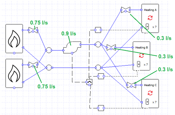
The total flow rate for the valves associated with the collections is 0.3 + 0.3 + 0.3 = 0.9, the same as the pump flow rate. So the problem probably isn’t related to the heating collections after all.
Let’s check the boilers: 0.75 + 0.75 = 1.5 l/s, which is inconsistent with the 0.9 l/s pump flow rate.
Consider what would happen where the boiler flows join before entering the pump; how could 1.5 l/s become 0.9 l/s? It cannot, so the simulation fails. On the other hand, on the other side of the pump there is no problem splitting 0.9 l/s into 0.3 + 0.3 + 0.3.
0.9 = 0.3 + 0.3 + 0.3
0.9 =/= 0.75 + 0.75
We could fix this easily by changing the boiler valve flow rates to 0.45 l/s each.
0.9 = 0.3 + 0.3 + 0.3
0.9 = 0.45 + 0.45
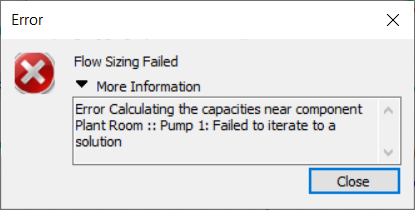
What if we encounter a message about an error calculating capacities?
We’ve already ensured that the flow rates are inconsistent. We now need to check either the component capacities, or pressure drops (note that only one or the other of these parameters will be specified at any time for a given component).
In this system we have specified a pressure drop for each component (and for the pump, a peak pressure value). As before, we should check the whole circuit and not just the component mentioned in the message.
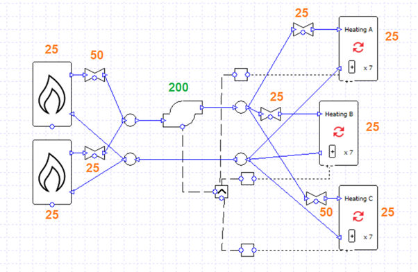
Whereas with the flow rates we needed to ensure that the total flow rates on either side of a junction are equal (e.g., 0.45 and 0.45 combining into 0.9), with the pressure drops we instead need to ensure that when flows split and join the pressure drops on the branching pipes are equal to one another. Let’s break this down further:
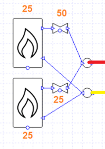
Here we have two branches. The flow returning from the heating collections (yellow pipe) reaches a junction and is split between the two boilers. Their flows then recombine and enter the red pipe.
The pressure drop on the top branch is 25 + 50 = 75 kPa. The pressure drop on the bottom branch is 25 + 25 = 50 kPa. 50 and 75 are not equal, so we need to edit the components to balance the equation (e.g., by changing the pressure drop of the top-most valve to 25 kPa).
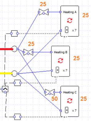
Meanwhile for the collections the flow from the pump (red) is split into three branches which recombine (yellow).
From top to bottom, the total pressure drop of the branches is:
25 + 25 = 50 kPa
25 + 25 = 50 kPa
50 + 25 = 75 kPa
50 and 75 are not equal. Again, we can change the pressure drop of the bottom-most valve to 25 kPa to remedy this.
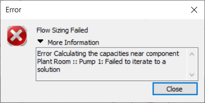
We would also receive an error message like this if the peak pressure of the pump was insufficient.
In this example, if every valve, boiler, and collection had a pressure drop of 25 kPa, we could draw the diagram below:
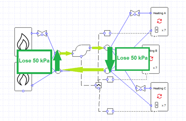
On a complete circuit the water loses 100 kPa of pressure and the pump has to overcome this; the pump peak pressure must be 100 kPa or more.
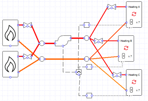
Now the design flow rates and pressure drops are in balance, and the pump is strong enough to move the water.
The schematic is rather messy. Is there a more elegant solution?
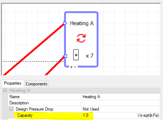
As the error messages above have hinted, the point of the design flow rates and design pressure drops is to get a flow “capacity” value for the components. You can choose to just type this in directly.
Note that this value is not really appropriate for this component, but it is convenient; more on this later.
This approach makes it very easy to split flows equally between branching pipes.
The valves have all been deleted and a capacity of 1 has been entered into each boiler and collection.
Note that we can now adjust the ratio of flow rates between branches very easily; for example, if the capacity of the boilers is in the ratio 5:1 then the flows will take on the same ratio.
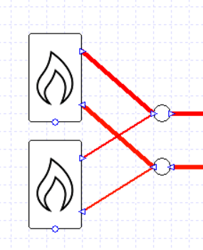
Note that this approach of using capacities will also work if we wanted to size the pump flow rate rather than specify it, as long as we set a delta T value to our collections and/or boilers.
One major downside of using capacities like this is it can be hard to get the correct pump load, which is related closely to pressure drop. By using such large capacity values, we have a negligible pressure drop and pump load. We can work around this by adding a valve in series with the pump which has a pressure drop representing the drop around the whole system, and whose flow is sized in the same way as the pump, either “Auto” (sized) or a fixed value:
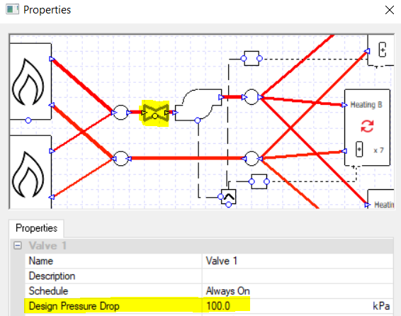
As before, if it is appropriate for our design, we can turn on the variable capacity option for the collections and do away with the controllers.
In the next blog post on this topic we will look at modelling primary and secondary loops.
