1 – Introduction
The purpose of this document is to outline some of the ways TAS Systems has the ability to model single zone VAV systems and their performance characteristics with particular reference to the Trane Engineering newsletter Volume 42-2, entitled ‘Understanding Single-Zone VAV Systems’. The newsletter can be found at the link listed below.
Trane Engineering Newsletter Volume 42-2
A single zone constant volume system traditionally uses a temperature sensor in the designated zone in order to vary the cooling and heating capacity, whilst the fan supplies a constant quantity of air. A single zone VAV system, on the other hand, uses the temperature sensor to vary the airflow delivered by the supply fan as well as the heating and cooling capacity in order to maintain the supply air temperature at a set point.
Single Zone VAV systems for the most part have been used for large, densely occupied zones that have varying cooling loads. These can include lecture halls, sports halls, and large meeting rooms. As a greater concern for energy consumption develops, single zone VAV is now being increasingly used in smaller zones such as offices, retail stores and classrooms, to take advantage of the energy saving capabilities that can be associated with single zone VAV (SZVAV) systems.
2 – Relevant ASHRAE Requirements
Requirements of the ASHRAE Standard 90.1 has certain specifications that single zone VAV systems must comply to. The requirements vary depending on whether cooling coils or direct expansion cooling is utilised. These are listed below;
- Air-handling and fan-coil units with chilled-water cooling coils and supply fans with motors greater than or equal to 5 hp shall have their supply fans controlled by two-speed motors or variable-speed drives. At cooling demands less than or equal to 50%, the supply fan controls shall be able to reduce the airflow to no greater than the larger of the following:
- One-half of the full fan speed, or
- The volume of outdoor air required to meet the ventilation requirements of Standard 62.1.
- Effective January 1, 2012, all air conditioning equipment and air-handling units with direct expansion cooling and a cooling capacity at AHRI conditions greater than or equal to 110,000 Btu/h that serve single zones shall have their supply fans controlled by two-speed motors or variable-speed drives. At cooling demands less than or equal to 50%, the supply fan controls shall be able to reduce the airflow to no greater than the larger of the following:
- Two-thirds of the full fan speed, or
- The volume of outdoor air required to meet the ventilation requirements of Standard 62.1.
3 – How Can TAS Meet These Requirements?
3.1 – First to model the system
The basic model for a single zone VAV system in TAS is shown in figure 1. This uses a heating and cooling coil to vary the temperature of the supplied air with an optimiser used to control the mixing of the outside air and the return air coming back through the system. The heating and cooling coils are controlled by the thermostat in the zone as well as reading the temperature leaving the fan in relation to heating and cooling setpoints.
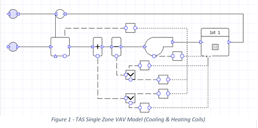
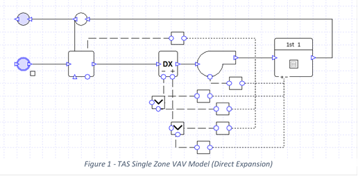
Figure 2 shows a very similar system that uses direct expansion for the heating and cooling in place of a heating and cooling coil.
3.1.1 – Optimiser (economiser) in place of dampers
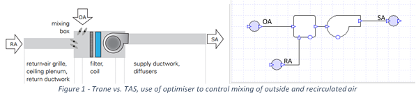
The Trane Engineering newsletter speaks of the implementation of dampers to control airflow. Although TAS has the ability to implement and control the dampers, in this single zone VAV model, TAS has a simpler method of control. An optimiser can be set up so that it will supply as much air as is necessary to the zone from mixing recirculated air and fresh air, whilst ensuring that the minimum fresh air for the zone is met. This is a simpler method for the user to control the ventilation in TAS systems. A complex control circuit would need to be made if dampers were to be used. Figure 6 shows the use of the optimiser in place of the mixing box the Trance Engineering newsletter references. This optimiser is used in both figures 3 and 4.
3.2 – Minimum flow fan speed – ASHRAE
TAS Systems has the ability to model both cooling and heating coils as well as direct expansion as a means of cooling and heating. The ASHRAE requirements are easily met by inputting some parameters into the software.
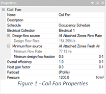
The requirement A is met in TAS by adjusting the fan properties in a model that uses a cooling coil to generate the cooling capacity. The fan is sized so that it can meet the maximum flow at any one time, whilst the minimum flow source is set to be 0.5x the design flow source. The other requirement, regarding outdoor air ventilation standards is set to ‘all attached zones fresh air’, which is specified in the occupancy conditions of the zone in TAS. In this case there is only one zone attached and the fresh air requirements never exceed one half of the full fan speed. The inputs for this are illustrated in figure 4.
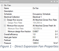
Requirement B is similarly implemented in TAS on a model that uses direct expansion to cool and heat the attached zone. The minimum flow on the fan is required to be two thirds that of the full fan speed. This is done by setting the minimum design flow fraction to be 0.6667. Similarly to the previous example, in this case the fresh air requirements will never exceed the two thirds of the full fan speed, meaning that the minimum fan flow rate will be 102.8 l/s during operating hours. The inputs for this are illustrated in figure 5.
3.3 – CO2-based demand-controlled ventilation
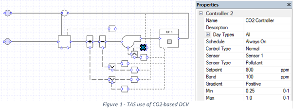
The Trane document outlines how single zone VAV systems are often used for zones that experience largely varying populations. As the population increases, this means the occupants produce more CO2. These zones can be controlled using a carbon dioxide sensor to maintain a comfortable working area with sufficient fresh air to breathe. A carbon dioxide sensor can be used to control an increase in the air flow when the CO2 levels exceed a specified level. This method is implemented into TAS Systems as shown in figure 6. The values for desired CO2 levels can be edited with ease. The blue cross marks the controller monitoring the carbon dioxide, which is located in the exit air stream from the zone being controlled.
Another method of controlling this would be to use a damper at the outside air inlet, controlling its opening by a similar CO2 sensor.
4.0 – Types of Fan control
There are varying methods of controlling single zone VAV systems including how and when they cool or heat and at what flow the supply fan will operate. The three main types of fan control to be looked at are:
- Constant-speed fan
- Two-speed fan control
- Variable-speed fan control
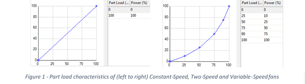
Each method of control is modelled separately in TAS Systems. The constant-speed fan model simply has no controller connected to the fan, meaning that it runs at the sized load whenever the system is in operation. Due to TAS using an hourly sampling system the two-speed fan control cannot be modelled as it would in a real system. This is because it would require instantaneous adjustment and calculation with relation to the flow rate. For this reason, the two-speed fan is modelled the same as the variable speed fan. This can be done because, if the fan speed is say 0.5x the full capacity, this means that a two speed fan will have been doing the same overall work but the speed output TAS gives can be interpreted as a proportion between the two fan speeds that it operates at.
The two-speed fan and the variable speed fan are distinguished in their energy consumptions by their differing part load characteristics. Load in a variable speed fan is not directly proportional the power. With a two-speed fan however, it can be assumed that each fan is operating at peak load, allowing it to be modelled by a directly proportional part load characteristic. The variable speed fan differs from this, in that under low loads it uses less power, meaning that it saves on power usage relative to the other two fan control methods.
The part-load characteristics are shown below in figure 7.
5.0 – Energy Savings Associated with SZVAV
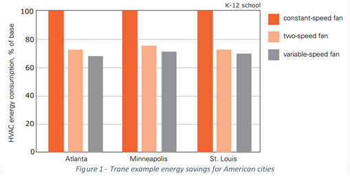
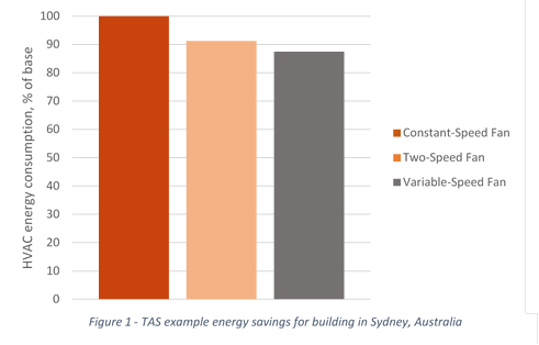
As stated and shown in the Trane engineering newsletter, energy savings can be expected by the utilisation of two-speed and variable-speed fans over the dated method of supplying the attached zone with a constant supply of air. Trane supplies results for three different types of fan system, showing how much energy could be saved with the implementation of the two improved fan control methods.
Below, figure 8 shows energy consumptions for a classroom in three different locations in America as given by Trane. Figure 9 shows energy savings as found by a simulation in TAS Systems with weather data taken for Sydney, Australia. It can be seen that from the two graphs energy savings are similar for the two-speed and variable-speed fans relative to the constant speed set up. The reasons for the different savings in the Trane and TAS models can be attributed to the varying building size, building layout, climate and operating hours that heavily influence the energy saved.
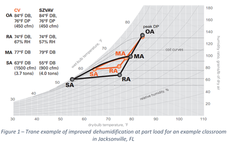
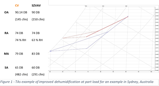
6.0 – Improved Part-Load Dehumidification with SZVAV
There is a noticeable difference in the performance of a constant volume system relative to a single zone VAV. The latter improves dehumidification performance at part load conditions.
Below in figures 10 and 11, it can be shown graphically via a Trane example and an example done using TAS systems.
At part load, the constant speed fan supplies a constant volume of air to the zone. As the sensible cooling load in the zone decreases, the compressor cycles on and off, resulting in warmer air being delivered to the zone. This results in a warmer average coil temperature, meaning that the warmer air has not been dehumidified as much as if it had been cooled more by the single zone VAV system.
The single zone VAV system, instead of switching off the compressor, reduces the supply airflow whilst still cooling to the same temperature. This allows more moisture to be removed from the air, giving better dehumidification to the zone. Although more cooling load is applied, more energy is saved from reducing the fan energy.
The dehumidification performance values from Trane and TAS Systems are given in Tables 1 and 2 respectively.
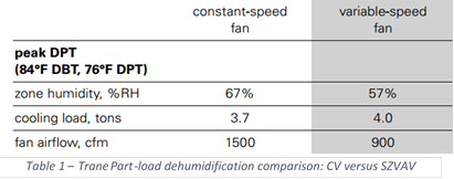
| Constant Speed Fan | Variable Speed Fan | |
|---|---|---|
| 84oF DBT | ||
| Zone Humidity, %RH | 74% | 63% |
| Cooling Loads, tons | 0.216 | 0.345 |
| Fan Airflow, cfm | 482 | 291 |