Drawing Dormer Windows

Windows which project from a pitched roof can be drawn without difficulty in the Tas 3D modeller. This short guide shows how to achieve this on five example models, using a methodical approach and knowledge of the “intersect planes” tool.

It is recommended that users should be familiar with different techniques for drawing roofs before following this guide. See here for more details.

Example 1

This is the easiest example, a flat-roofed wall dormer. The face of the dormer is coplanar with the external wall and there is no roof void to worry about.

Firstly, create the planes which will define the pitched roof. (On the “drawing utilities” tab, under “3D planes”, use the tool “by points”). Do not apply any planes at this stage.

Now create a plane where all points are equal to the height of the flat roof over the dormer. The reason will become clear in the next step.

Select the space. On the “drawing utilities” tab, under “3D planes”, find the tool “intersect planes”. Select the pitched roof plane and the horizontal plane which you have just created.

This will create a null wall across the space where the pitched roof and flat roof will intersect. From this line, draw null walls to the external wall (on a real project, refer to your drawings for the dormer side wall positions).

Place the window.

Recommended but optional: Clean up null lines.

Now apply the 3D planes. Note that for the flat roof over the dormer you can either use the horizontal plane created earlier or just enter a value for the space height.

Apply zones. Create the 3D analysis model.

In the list of building elements, change the null-exposed element to represent an external wall. Be sure to assign an appropriate construction to this building element in the TBD.

Finished!

In the following examples you can see how these techniques can be used to model window types that could seem challenging at first glance.

Example 2

Here we have a gable-fronted wall dormer. The face of the dormer is coplanar with the external wall and there is no roof void to worry about. But we do have to deal with two pitched roofs over the dormer – this is not a major obstacle as long as we remember how to use the intersect planes tool.

As in the previous example, begin by creating the planes which will define the main pitched roof.

Draw null lines marking the middle and limits of the dormer (on a real project, follow your drawings).

Create the planes which will define the pitched roof over the dormer. Note that it doesn’t matter if the points selected are not within the limits of the dormer’s location according to your drawings – as long as the points are on the correct line, the planes will intersect correctly with the main roof plane to define the dormer limits.

Select one of these spaces and intersect the corresponding dormer roof plane and the main roof plane. Do the same for the other space.

Place the window. Clean up null lines. Apply 3D planes.

Apply zones. Create the 3D analysis model. In the list of building elements, change the null-exposed element to represent an external wall.

Finished!

Example 3

This is similar to example 2 but we have the added complication of a roof void in some parts of the space. Thankfully, the use of 3D planes means the voids will not make our task any more difficult.

Firstly, create the planes which will define the main pitched roof. Draw null lines marking the middle and limits of the dormer (on a real project, follow your drawings).

Create the planes which will define the pitched roof over the dormer.

Select one of these spaces and intersect the corresponding dormer roof plane and the main roof plane. Do the same for the other space.

Draw the internal walls which separate the occupied space and the roof void (on a real project, follow your drawings). Also change the sides of the dormer to internal walls so that a solid wall separates the occupied space from the roof void.

Place the window. Clean up null lines. Apply 3D planes. Note that you can select multiple spaces and assign the same plane to them at the same time.

Apply zones. Create the 3D analysis model.

In the list of building elements, change the internal wall-exposed element (and if necessary, null-exposed element) to represent an external wall. Be sure to assign an appropriate construction to this building element in the TBD.

Finished!

Example 4

By now you can probably see how these techniques can be easily applied to a situation where a dormer window is set back from the external wall. Here we have another gable-roofed dormer and roof void situation, but the window is not coplanar with the external wall.

Firstly, create the planes which will define the main pitched roof. Draw null lines marking the middle and side limits of the dormer (on a real project, follow your drawings).

Create the planes which will define the pitched roof over the dormer. Note that it doesn’t matter if the points selected are not within the limits of the dormer’s location according to the plans – as long as the points are on the correct line, the planes will intersect correctly to define the dormer limits.

Select one of these spaces and intersect the corresponding dormer roof plane and the main roof plane. Do the same for the other space.

Draw the internal walls which separate the occupied space and the roof void (on a real project, follow your drawings). Change the sides of the dormer to internal walls. Draw an internal wall (not external) at the face of the dormer (on a real project, follow your drawings).

Place the window. Clean up null lines. Apply 3D planes.

Apply zones. Create the 3D analysis model. In the list of building elements, change the internal wall-exposed element (and if necessary, null-exposed element) to represent an external wall.

Finished!

Note how the different treatment of “internal wall” and “internal wall-exposed” allows us to have one building element separating the occupied space from the void space, and a different building element separating the occupied space from the outside air.

Example 5

Here we have a hip roof dormer set back from the wall, with a roof void. This is the most complicated example but by now you probably see clearly how to model it. Essentially this is the same as the previous example but with an additional step for the additional plane.

Firstly, create the planes which will define the main pitched roof. Draw null lines marking the middle and side limits of the dormer (on a real project, follow your drawings). Create the planes which will define the pitched roof over the dormer.

Draw an internal wall (not external) at the face of the dormer (on a real project, follow your drawings).

Draw a null line which intersects the dormer centre-line at the apex of the pitched roof over the front of your dormer (on a real project, follow your drawings).

Create the plane which will define the pitched roof over the front of the dormer.

Intersect planes twice. Intersect the front dormer plane with the first dormer side plane. Intersect the front dormer plane with the second dormer side plane.

Clean up null lines. This ensures nothing will interfere with intersecting the main roof plane and the dormer side planes.

Intersect the dormer side roof planes and the main roof planes.

Draw the internal walls which separate the occupied space and the roof void (on a real project, follow your drawings). Change the sides of the dormer to internal walls.

Place the window. Clean up null lines. Apply 3D planes.

Apply zones. Create the 3D analysis model. In the list of building elements, change the internal wall-exposed element (and if necessary, null-exposed element) to represent an external wall.

Finished!

Applying the techniques demonstrated in these examples will allow you to model any dormer window type you are likely to encounter.

Drawing Roofs

There are many options for drawing roofs in the Tas3D modeller. This short guide explains when each option may be the best choice and clears up some common questions.

Option 1: Set Wall Height
Pros: A very quick solution for simple sloped roofs with a level ridge.
Cons: Unsuitable for any other type of roof.

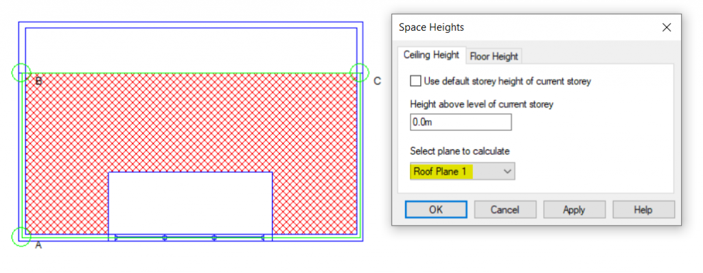
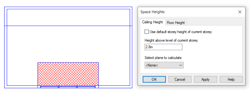
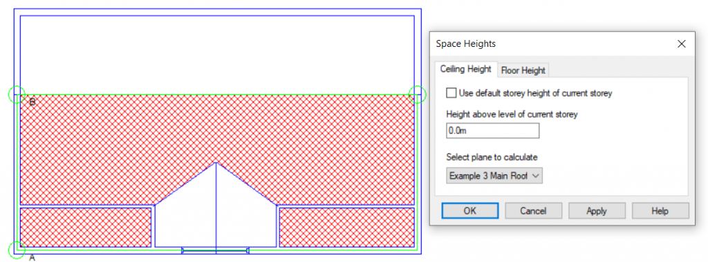
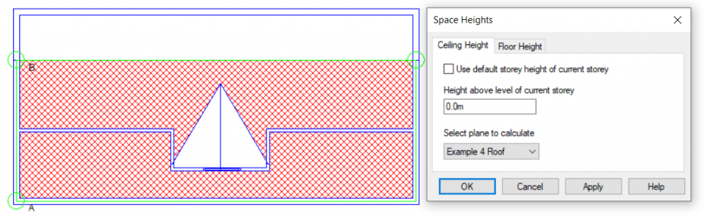
Option 2: Set Space Height
Pros: A very quick solution for stepped flat roofs.
Cons: Unsuitable for sloped roofs.

Option 3: Set Point Height (Select Join)
Pros: Allows quick modelling of curved roofs and intersecting slopes.
Cons: Can be time-consuming with roofs that cannot be triangulated easily. Not suitable when there is an abrupt change in roof level.

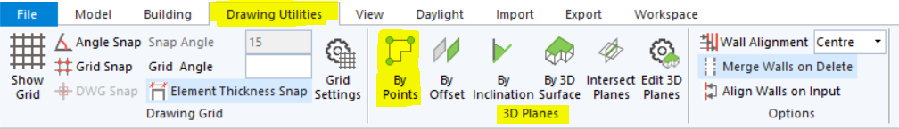
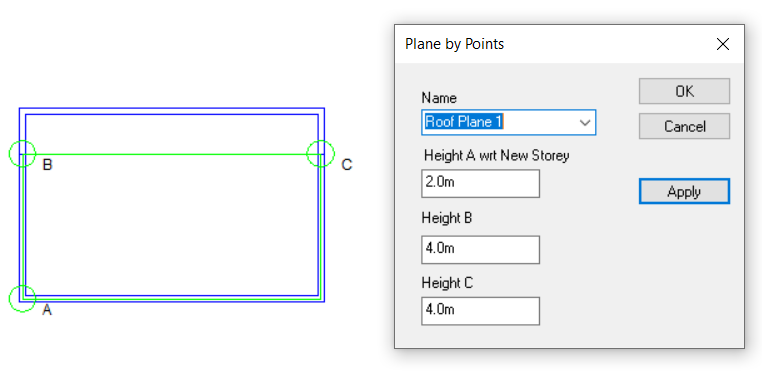
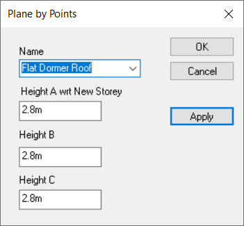
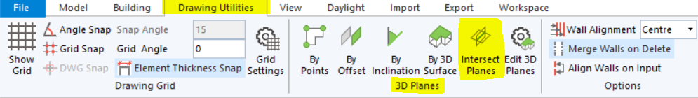
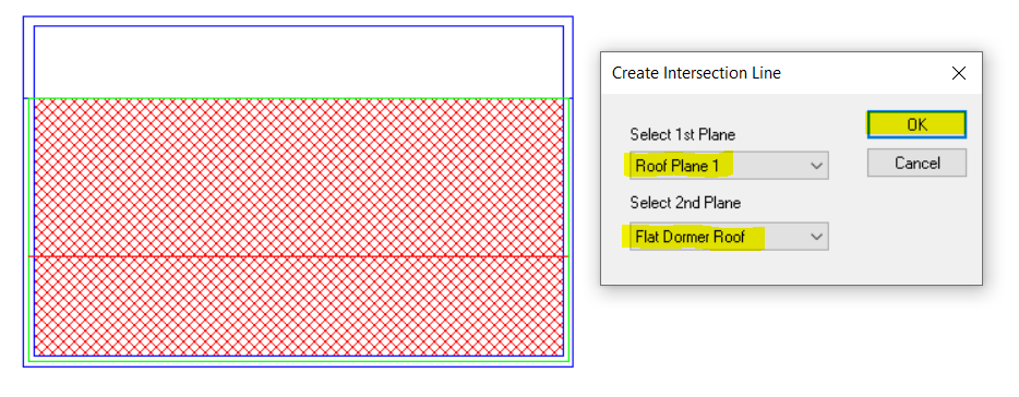
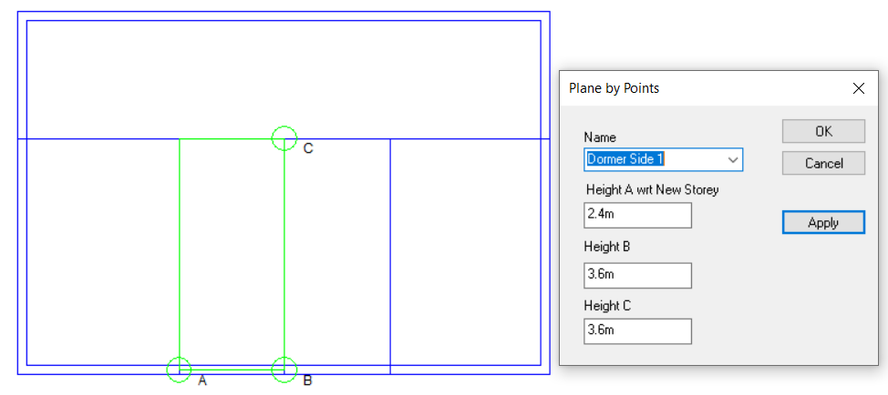
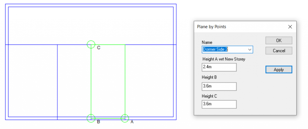
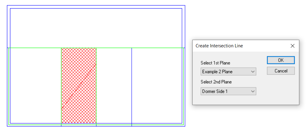
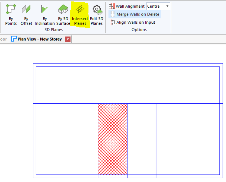
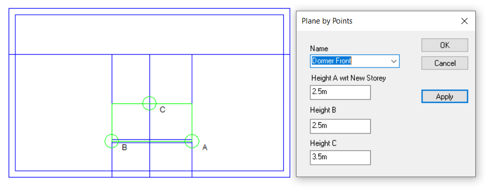
Option 4: Use 3D Planes
Pros: Can be applied to any sloping roof situation. Plane can be used for multiple roof areas at once. Intersection line between two planes can be calculated automatically. Reduces risk of errors arising from incorrect wall and point heights.
Cons: Creating the planes can be more time-consuming than the other methods.

Examples

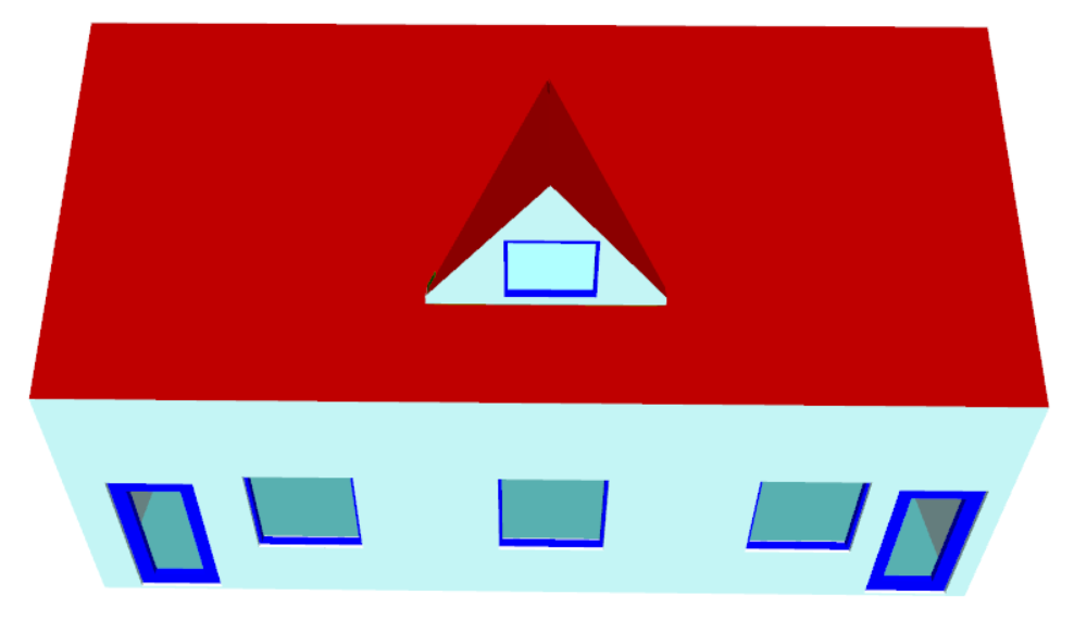
How would three different roofs be modelled most effectively on this simple building?

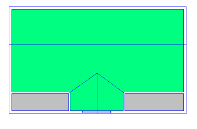
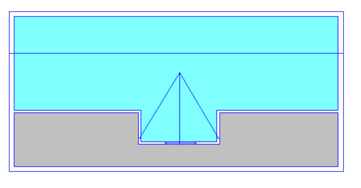
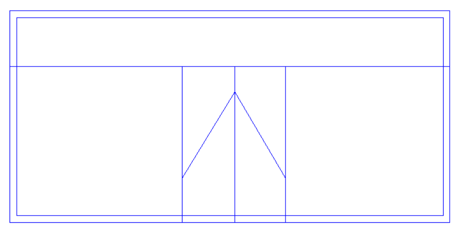
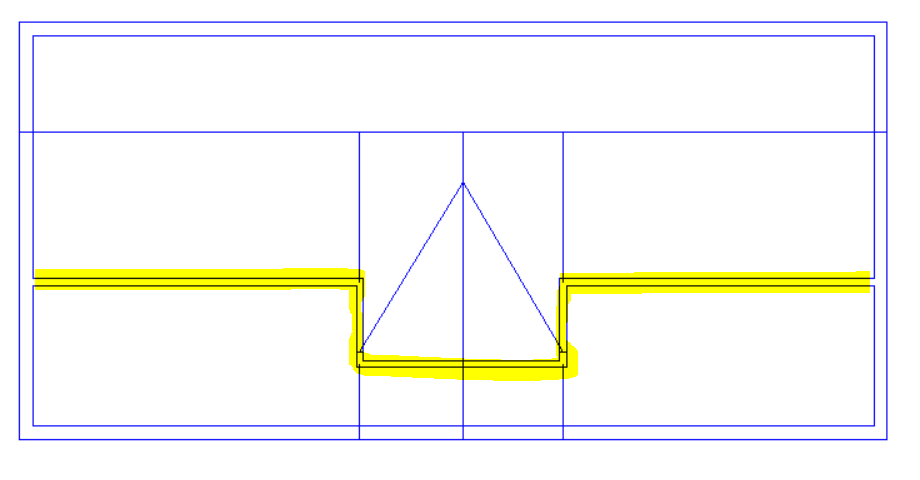
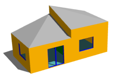
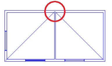
With this roof there is a sudden change in roof level, and the “Set Point Height” option cannot be used. We can see why if we consider one of the points used by both sloping roofs (highlighted in lower image) which would need to have two different roof heights at the same time; in this example it would need to be 4.5m for the left-hand roof and 5.5m for the right-hand roof.

We need to use 3D Planes here.

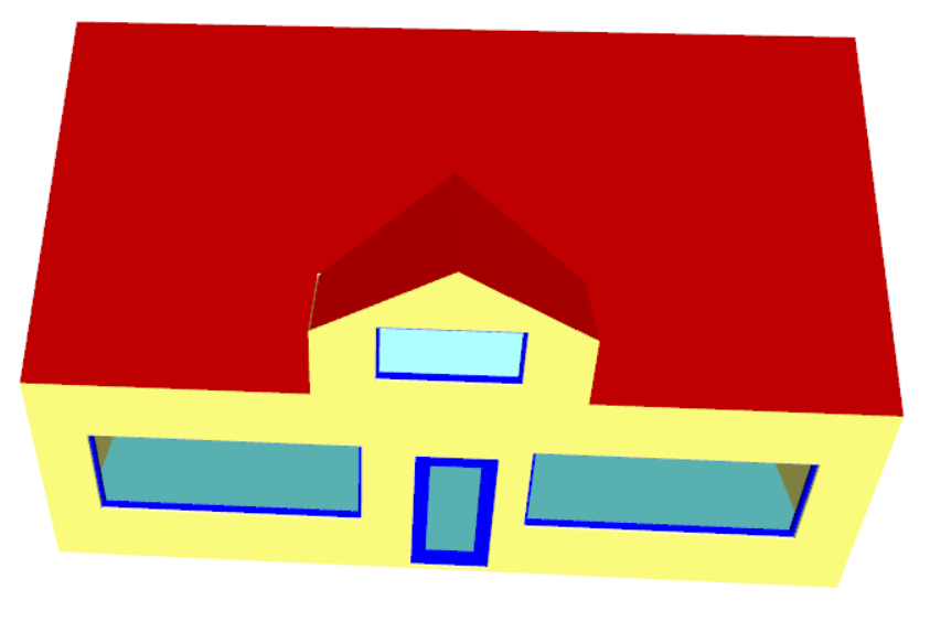
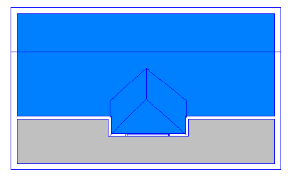
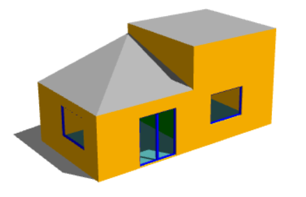
With this example we have a sudden change in roof level, meaning that once again we have points which would need to have two different heights at once; we cannot use the “Set Point Height” option.

In this case we would need to use 3D Planes for the left-hand roof. For the right-hand roof we can simply use the “Set Space Height” option.

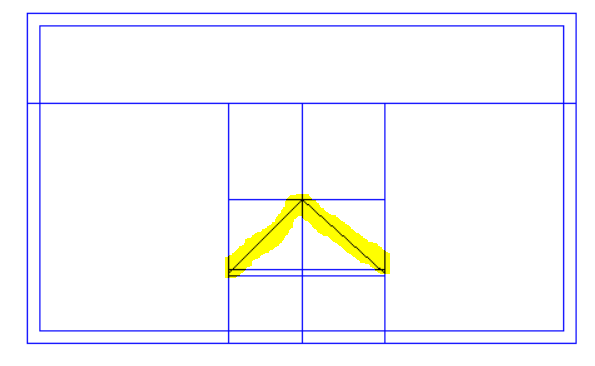
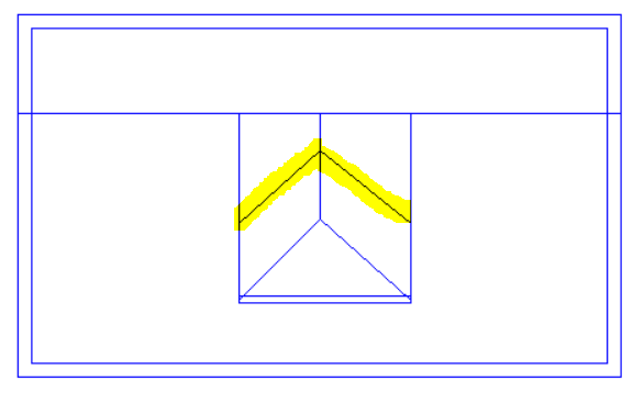
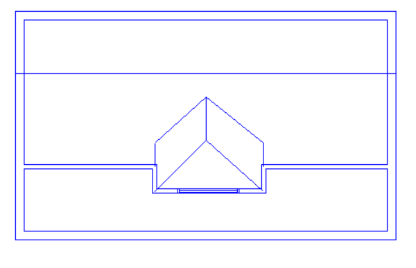
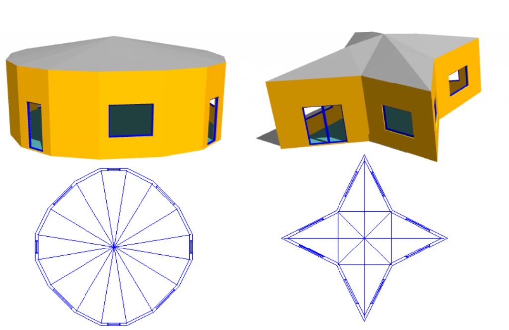
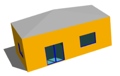
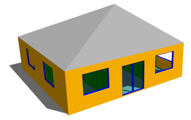
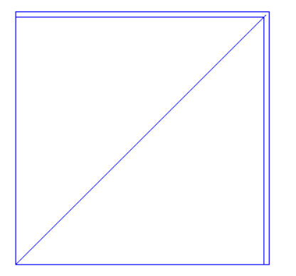
This roof rises to a single point and there is no step or sudden change in roof level. The roof can be achieved easily by using the “Set Point Height” option.

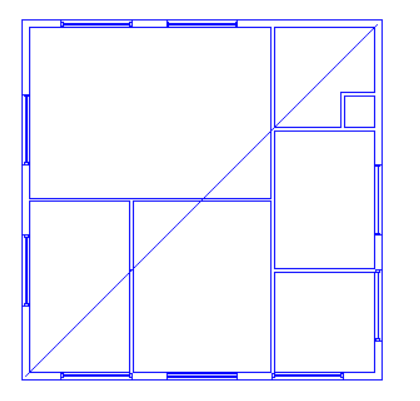
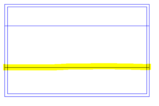
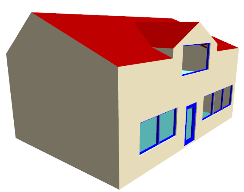
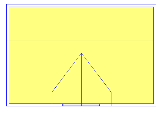
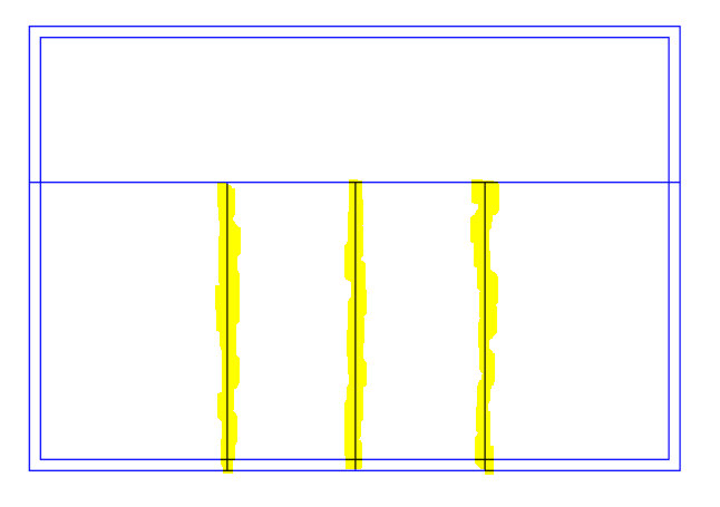
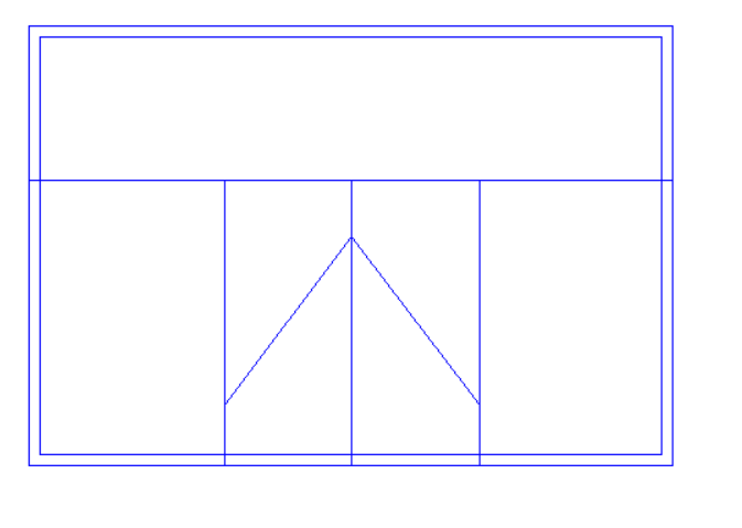
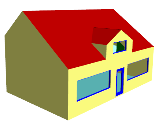
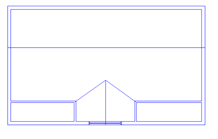
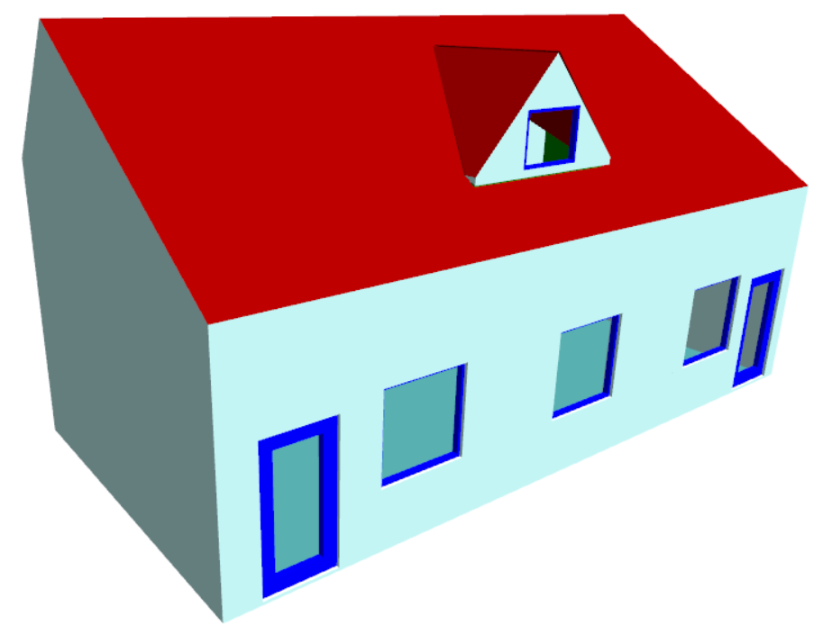
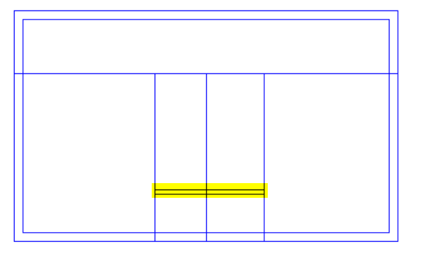
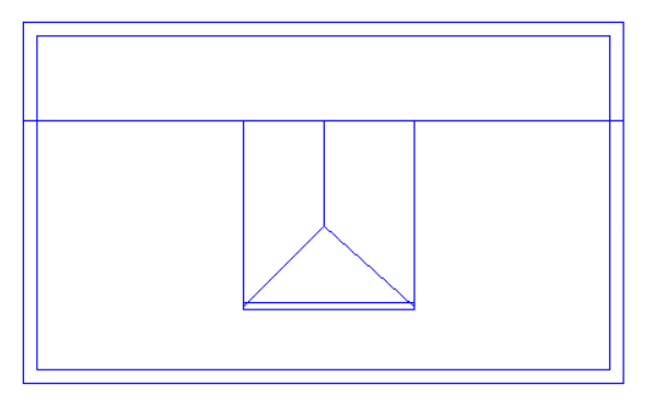
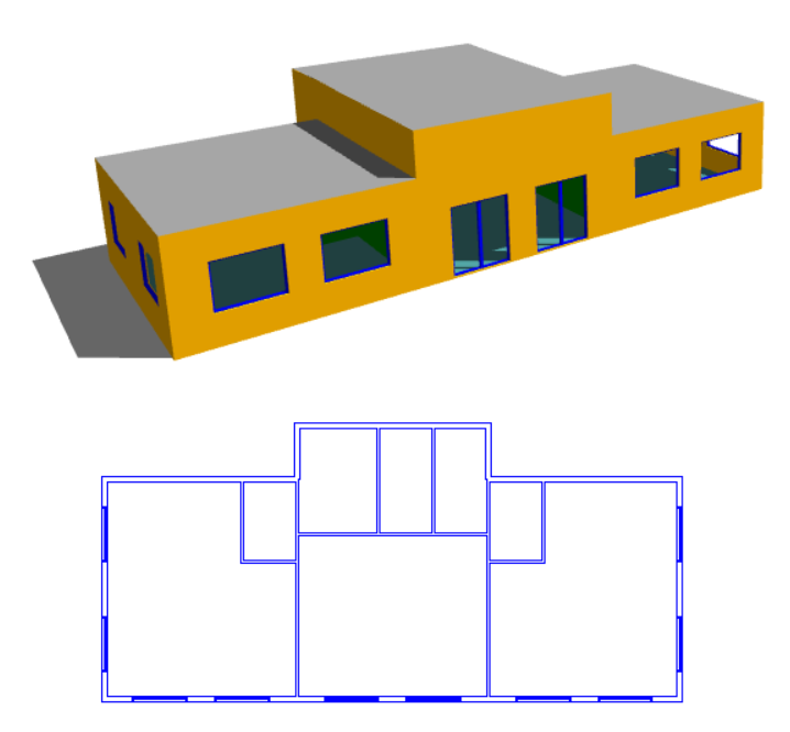
What about a situation where the roof itself is very simple, but there are several internal walls underneath it?

The answer depends on whether or not the roof is on a separate storey. In the case where the internal walls extend upwards to meet the underside of the sloping roof, the best option is to use 3D Planes. But if there is a separate roof space and the internal walls only extend to the underside of a flat ceiling, we should model the roof on a separate storey and the “Set Point Height Option” can be used.

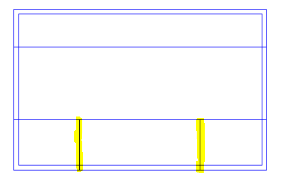
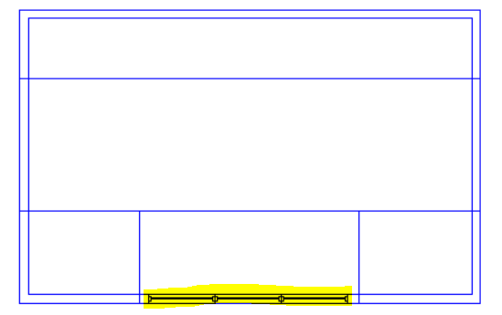
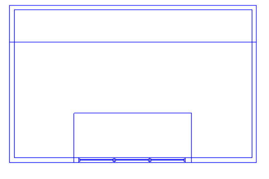
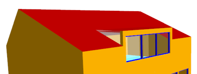
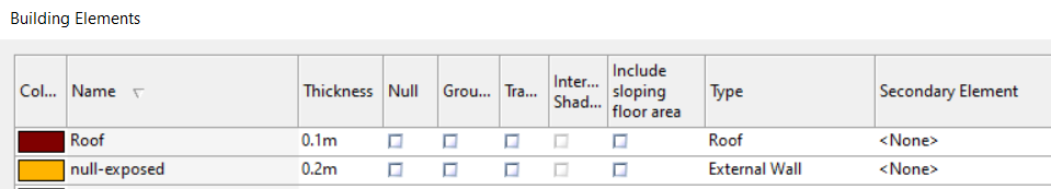
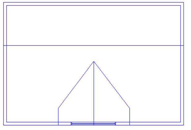
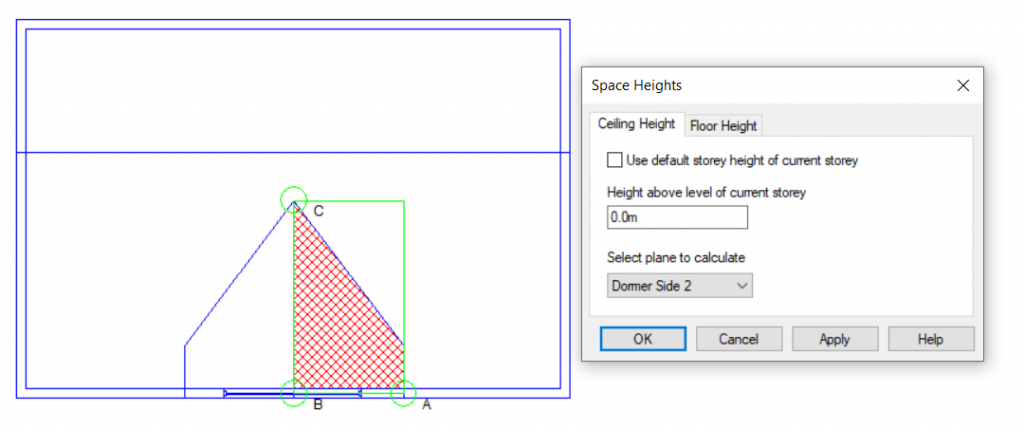
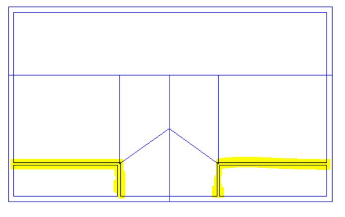
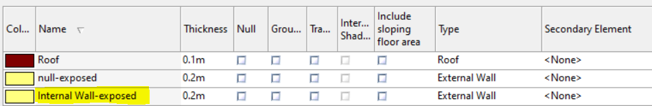
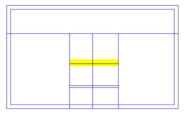
What about “gaps” in the roof where internal walls or null lines are exposed?

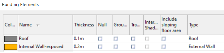
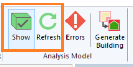
When you create the analysis model, Tas3D creates a new building element for the exposed parts of internal walls, null walls, etc. These new elements, which will have a name ending in “-exposed” can be changed by the user to represent external walls (or, depending on your building, you may want to set these up to represent, e.g., glazing). When you refresh the analysis model you will see that your roof “gaps” have been filled. Be sure to assign an appropriate construction to these building elements in the TBD.