Using the 3D Visualisation to help sanity check your TBD file
Setting up the TBD correctly is a vital part of carrying out any thermal modelling in Tas, whether it’s for an L2 & EPC assessment, an overheating assessment or an energy model. It’s very important that the TBD file is set up appropriately for the analysis being carried out, as any errors or mistakes in the TBD could impact the results of the analysis and thus invalidate them. Ultimately it is the users responsibility to ensure that the correct constructions, internal conditions, apertures etc. are applied throughout the model, but Tas does have some great tools to assist with this.
The TBD file does give errors and warnings for a number of things when you run the pre-simulation checks under Tools in the toolbar, as shown in the image below.
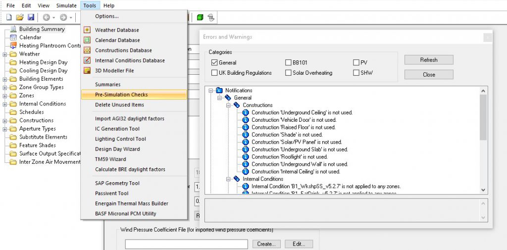
The pre-simulation checks are a brilliant tool for highlighting common omissions and mistakes, it is a great place to start when performing a sanity check of the model but they are not able to decipher when the wrong information has been applied in the model. For example you would get an error message if no construction is applied to the windows but if you have applied the ground floor construction to your windows accidentally, the pre-simulation checks will not detect this.
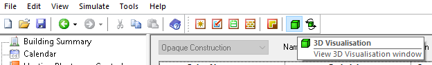
The 3D Visualisation is a great tool to sanity check many components of your model and we strongly recommend using it to aid in checking your TBD is set up correctly. If you click on the 3D Visualisation icon in the toolbar (as shown in the image below) the 3D Visualisation window will appear with your building geometry displayed.
Only zoned areas of the building will be displayed in the 3D Visualisation. If there are areas of the building missing that you think should be included in the analysis you will to check these are zoned correctly in your 3D modeller file, then re-export and merge with your TBD file. Right clicking in the 3D Visualisation window will allow you to change the settings of the 3D Visualisation, you’re able to adjust the display colour of the visualisation to be based on a number of options including zone colour.
Using the 3D Visualisation to check building elements
While the 3D Visualisation window is open you can expand the building elements folder in the tree-view and click one of the building elements, this will highlight where this building element is applied in the model. This is a quick way to check the correct building elements have been applied to the correct surfaces. If you have 2 external wall types, for example, with differing constructions and U values, you can highlight each of these separately and ensure that the model has these assigned in the correct areas.
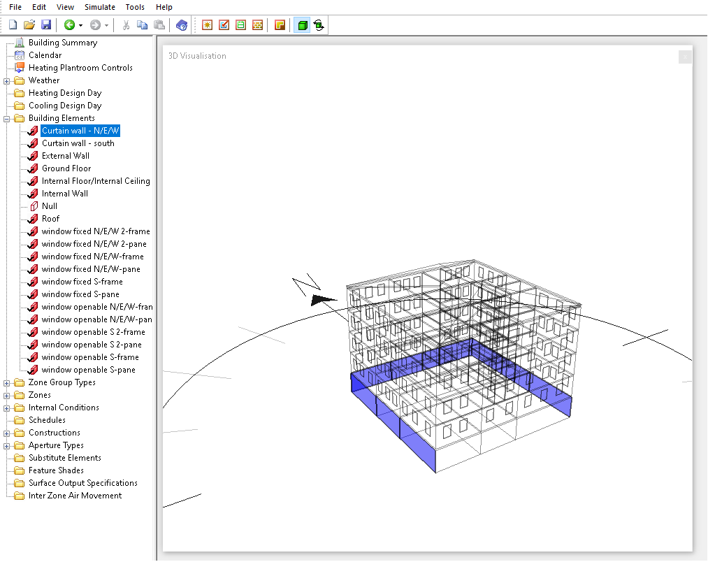
By highlighting the “curtain wall N/E/W” building element I can quickly see that this element has been applied in the right locations and hasn’t been applied to the south facing curtain walling.
If you have any building elements for which you are unsure what construction to apply, you can use this feature to find where the building element is applied and then choose the appropriate construction.
Using the 3D Visualisation to check zones & internal conditions
Expanding the zones folder in the tree-view and selecting a zone will highlight this zone in the visualisation. You can quickly cycle through the zones using the arrow keys on your keyboard to check the zones in the model have been applied to the correct areas of the building. If you have any HVAC groups, Zone groups or Zone sets created in the model selecting these in the tree view will highlight all zones assigned to this group simultaneously. This feature can be useful to check the correct zones have been assigned to each group, for example if you have a HVAC group called “3F VRF” and see that there is GF zone applied to this in the visualisation you know this will need looking into.
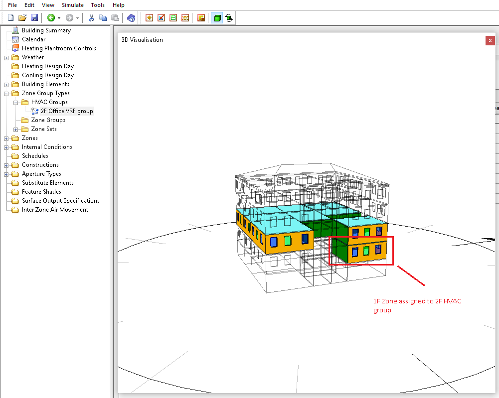
Here I can see that there is a 1F zone assigned to the HVAC group “2F Office VRF group”, I can now look into ensuring the 1F zone is assigned to the correct HVAC group.
Checking the locations of the zones in the model using the visualisation is also a great way to find any non-contiguous zoning. You will likely get a warning about non-contiguous zoning in the pre-simulation checks if this is present in your model but highlighting the zone and its location in the 3D Visualisation is the quickest way of locating the issue.
Highlighting an internal condition in the tree view will highlight all areas where this is applied in the geometry, for larger models this may not be very useful as it will be hard to check the correct areas have this internal condition applied visually but it can be useful for smaller models as shown below.
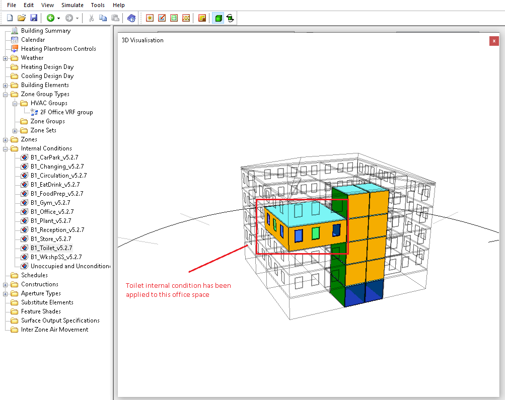
By highlighting the toilet internal condition I can see there is a large space on the 3F that has incorrectly been assigned the toilet internal condition, this space should have the office internal condition applied.
Using the 3D Visualisation to check construction and aperture types
Selecting a construction in the tree view will highlight all surfaces this has been applied to. Cycling through the constructions using the arrow keys while the 3D Visualisation window is a fantastic way to sanity check the constructions assigned in the model. This feature is key to finding instances in which an incorrect construction has been assigned, for example if you have a different glazing specification for south facing glazing you can easily identify any cases of this being applied to the wrong façade(s).
If you have a ceiling void modelled in the 3d modeller but have applied the default internal floor building element to this space and applied the default internal ceiling element to the space below this will likely come through as an internal floor/internal ceiling in the building simulator. It’s quite likely that the construction between a void and the space below will be different to the construction between one occupied floor and another and any cases of the incorrect construction being applied can easily be identified.
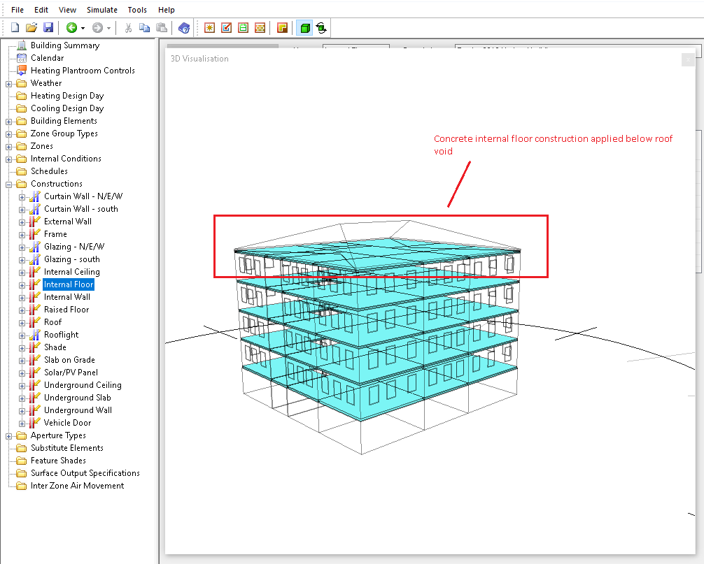
Here I can see that the same internal floor construction has been applied between occupied floors and between the 4F and the void space above. I know that the construction between the 4F and the void is not a concrete floor and is plasterboard so I can amend this.
Selecting an aperture in the tree view will unsurprisingly show all instances where this aperture is applied in the 3D Visualisation, this is useful for checking you haven’t accidentally assigned the aperture to any incorrect building elements.
“Top-tip”: if you change the colour of all openable windows to one colour in the 3D modeller file you can quickly check the correct windows have apertures assigned using this feature.
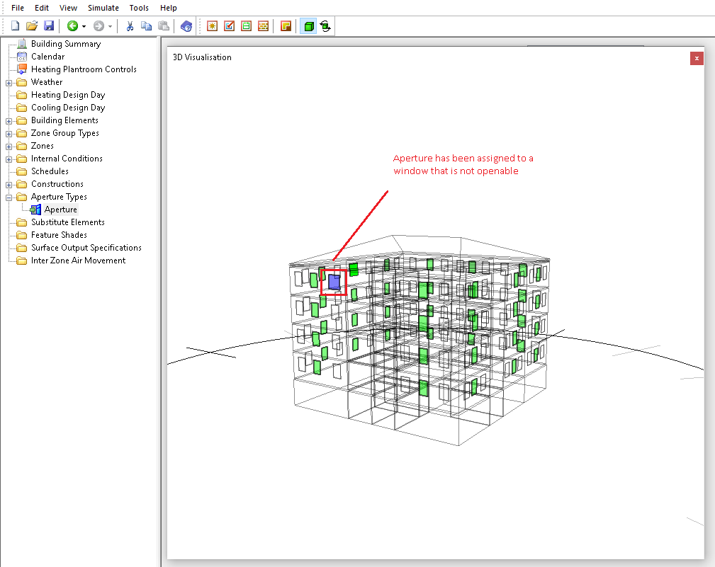
Because I know I made all of the openable windows green in the 3D modeller file I know that the blue window has incorrectly been assigned the aperture function in this model and it needs to be removed from this building element.
The 3D Visualisation is a great tool for quickly checking your TBD file for errors which could otherwise be easily over-looked. If you’re not currently a Tas user but are interested in trying out our software you can get a free trial from our website, because we are unable to offer our usual face to face software training our e-training is currently all free!